ROS Wi-Fi Burner Management System
User Manual
Setup, configuration, and operational guidance for flares, combustors, and heater treaters in Permian Basin service.
Quick Start (5 minutes)
This quick start is intended for commissioning and functional checkout. Always follow your site safety policies, electrical codes, and equipment OEM requirements.
- Mount & power: Mount the enclosure securely. Apply 12V or 24V DC per your configuration.
- Connect to Wi-Fi: Join SSID flame (default) using password 12345678.
- Open the UI: In a browser, go to igniter.local. Bookmark for repeat access.
- Select application: Choose your mode (flare, combustor, heater treater, igniter feedback/no-feedback as applicable).
- Set sensing + ignition: Select flame proving method (thermocouple and/or ionization) and ignition type (spark/HEI/glow).
- Apply settings: Save configuration in the UI.
- Run functional test: Confirm pilot, main, and aux/ESD outputs (as configured) behave as intended; verify flame proving and lockout response.
- Secure the system: Change SSID/password and restrict access to authorized personnel.
Safety & Responsibilities
- Qualified personnel: Installation and commissioning should be performed by trained technicians familiar with fired equipment controls.
- Verify I/O: Confirm each output controls the intended device (pilot valve, main valve, ignitor, ESD where used) before enabling automatic sequences.
- Lockout discipline: Treat lockout events as abnormal operations requiring inspection and corrective action before restart.
- Site policies: Follow your operator's hot work, LOTO, and startup procedures and documentation requirements.
System Overview
ROS BMS provides local Wi-Fi access for configuration and status viewing, with support for common oilfield fired equipment use cases (flares, combustors, heater treaters). Typical functions include:
- Outputs: ignition device control and valve/solenoid control (pilot/main/aux as configured).
- Flame proving: thermocouple (temperature trend) and/or ionization (flame rod/electrode) depending on configuration.
- Status outputs: analog outputs such as 4–20 mA or 1–5 V for temperature/status signaling (where used).
- Event history: run-time indicators, alarms, and lockout reasons (feature availability depends on deployed firmware/UI).
What "Proving" means
Flame proving is the controller confirming that ignition resulted in a stable flame within a defined time window. If proving fails (or is lost during operation), the controller should close gas valves and enter lockout per your configuration.
Connecting (Wi-Fi)
What you'll need
- Wi-Fi capable smartphone/tablet/laptop
- Powered BMS (12V or 24V DC)
- Modern browser (Chrome, Safari, Edge)
Step-by-step
- Power on the BMS and confirm the unit is energized (indicator light behavior varies by build).
- Open Wi-Fi settings and join the BMS SSID (default: flame).
- Enter the default password: 12345678.
- Open a browser and navigate to igniter.local.
- Bookmark the page for quick return access during commissioning and PM visits.
Common connection issues
- igniter.local not loading: confirm you are connected to the BMS Wi-Fi network (not a site Wi-Fi). Try another browser and disable "Private Relay" features that can affect local resolution.
- Weak signal: move closer or reposition antenna/enclosure per site constraints. Large metal structures can attenuate Wi-Fi.
Specifications
If your unit is configured differently (I/O count, wiring, or scaling), use the shipping documentation or configuration screen as the source of truth.
Installation & Wiring
Mounting
- Select a location protected from direct impact and excessive vibration.
- Maintain clearance for cable bends, service access, and enclosure door swing.
- Route low-level sensor wiring separately from ignition/high-noise conductors where practical.
Wiring guidelines (field best practices)
- De-energize before wiring: confirm power is OFF and conductors are de-energized.
- Shielding: use twisted pair/shielded cable for thermocouple and ionization runs where feasible.
- Grounding: bond the enclosure to site ground per operator and electrical code requirements.
- Labeling: label each conductor (pilot valve, main valve, ignitor, ESD) to reduce troubleshooting time.
Field Wiring Reference (Front Board)
This terminal map mirrors the ROS controller backplate (rev 2026-02-09). The left plug carries outputs, the ignition coil, and power; the right plug carries the sense circuits (flame rods, thermocouples, flame stat, process control). All ground returns land at a single star-ground node.

Left plug — outputs / coil / power
Right plug — sense / telemetry
Critical wiring rules
- Spark return and sense return stay separate until the star-ground node. Never daisy-chain the coil-secondary return through the flame-rod return.
- Flame-rod leads are shielded; ground the shield at the panel end only and leave the rod-end shield floating.
- Mount the ignition coil at the pilot where feasible so only the low-voltage primary runs the stack; keep the HV secondary lead short.
- All grounds — chassis, signal source, burner base, coil-secondary return, TC returns, and earth rod — land at the single star node and nowhere else.
Flame Rod (Ionization) Wiring
Single-rod sensing (spark and flame-sense sharing one electrode) exposes the microamp ionization input to the kilovolt ignition pulse, causing nuisance lockouts and progressive damage to the sense circuit. The ROS controller provides dedicated Flame Rod 1/2 ionization inputs separate from the Coil Secondary (HV) terminal. Wire dual-rod so the sense input never sees the spark.
Grounding (single-point / star)
- All returns — spark/coil-secondary return, ionization sense return, thermocouple return, chassis, and earth — meet at one defined star-ground node and nowhere else.
- Never daisy-chain the spark return through the sense return. A shared return is the primary cause of spark noise corrupting the microamp flame signal.
- Burner ground electrode (Burner Base) area must be much larger than the sense-rod area, or the rectified signal will be weak — especially on wet casing gas.
Field maintenance — casing gas
Wet/variable field gas soots the flame rod faster than clean fuel, producing a weak or dropping signal that mimics flame loss. Include flame-rod cleaning in the PM interval; clean with fine abrasive cloth only — do not use a scrubbing pad, which leaves a residue that inhibits the microamp signal. Confirm a solid burner ground at each PM; a marginal ground is the most common cause of weak rectification.
Flare Pilot Ignition — Coil on the Pilot Carriage
Applies to retractable flare pilots. The ignition lead and the flame-sense lead travel up and down the stack together as the pilot extends and retracts. When the coil sits in the panel, its kilovolt secondary runs the full stack length parallel to the microamp sense lead, and energy couples into the sense circuit — corrupting the flame reading, causing nuisance lockouts, or in the worst case false-proving flame (a failure-to-danger condition). Because the pilot is retractable, conduit cannot be run up the stack, which removes the simplest shielding option.
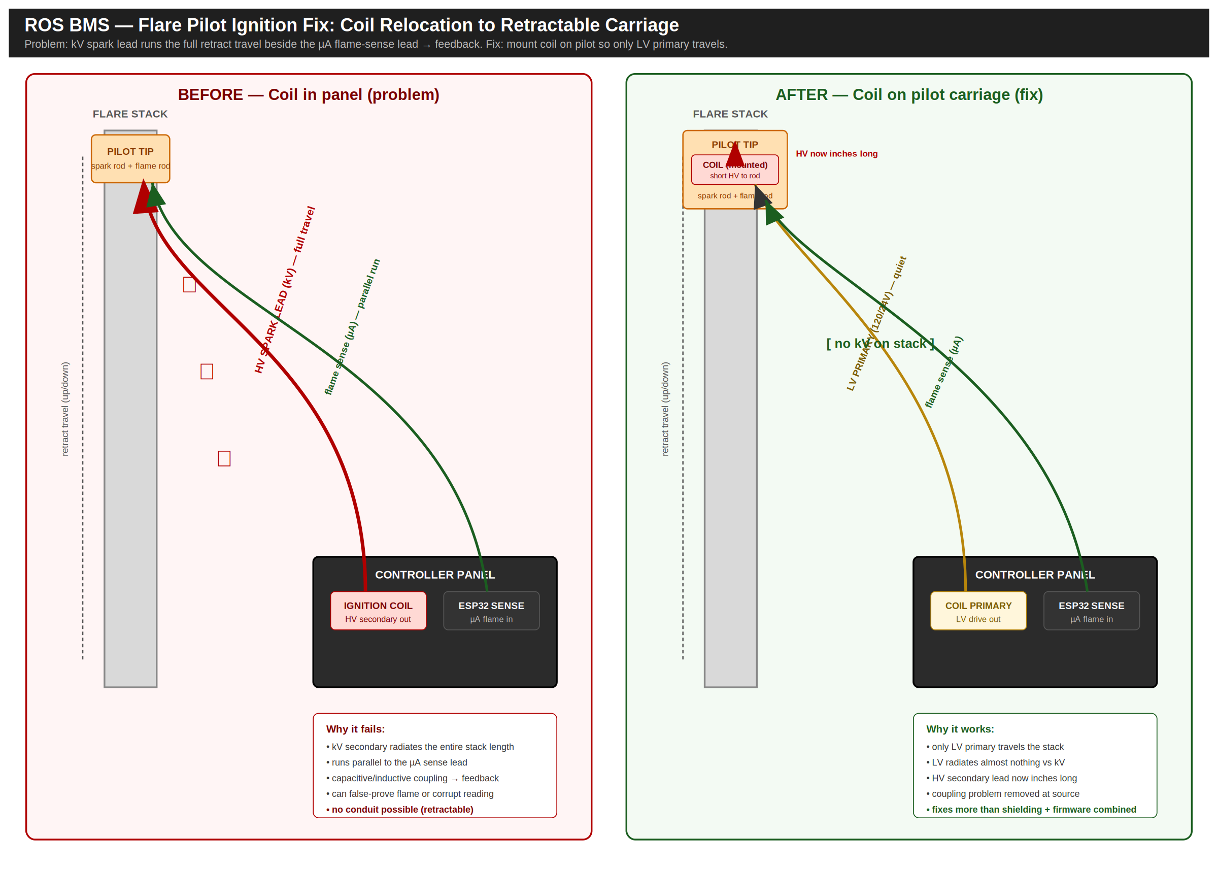
Why the usual mitigations fall short here
- Physical separation: the standard 6–8 in between HV and sense leads is not achievable when everything runs up the same riser.
- Conduit/raceway: rigid conduit cannot flex with a retractable pilot.
- Shielded flexible cable: reduces coupling but does not eliminate it, and adds cost and flex-fatigue risk on a moving bundle.
The fix — relocate the coil
Mount the ignition coil on the retractable pilot carriage. Only the low-voltage primary (120 V or 24 V) then travels the stack beside the sense lead — LV primary radiates almost nothing compared to a kilovolt secondary. The HV secondary becomes a short, fixed lead from coil to spark rod: inches long instead of the full stack travel. This resolves more than shielding and firmware mitigation combined.
Install checklist
Configuration
Configuration is performed through the local UI at igniter.local. Typical steps:
- Select the application: flare, combustor, heater treater, etc.
- Select ignition type: spark, HEI, or glow plug (as equipped).
- Select flame sensing: thermocouple and/or ionization (flame rod/electrode).
- Set timing: ignition frequency and durations appropriate for the application and fuel quality.
- Set shutdown thresholds: high-temperature shutdown and other interlocks (where used).
- Apply/save: persist settings before running.
Recommended commissioning checklist
- Confirm all sensors read plausibly (no open/grounded faults).
- Verify valve outputs open/close correctly and return to safe state on ESD/lockout.
- Verify flame proving occurs within the expected window and fails safely when flame is absent.
- Record final settings on the Commissioning Record and provide to the operator for documentation.
Operation
During normal operation, the controller sequences ignition and verifies flame presence. The UI can be used to view:
- Current mode (running/stopped/lockout)
- Ignition state and retry counts (where shown)
- Flame sensing status (ionization/thermocouple)
- Temperature readings and shutdown thresholds
- Valve/solenoid state (pilot/main/aux as applicable)
Operator workflow (typical)
- Verify prerequisites: fuel availability, ESD permissives, and site readiness.
- Start sequence in the UI (or via configured control input where used).
- Confirm pilot ignition and flame proving.
- Confirm main opens only after pilot is proved (application-dependent).
- Monitor temperatures and status for the first several minutes after startup.
Alarms & Lockout
Lockout is a protective state. The controller should close valves and require operator action before restart.
Actual alarm names and behavior may vary by firmware and application profile.
Troubleshooting
Wi-Fi / UI access
- SSID: flame (default)
- Password: 12345678 (default)
- UI: igniter.local
- Setup page: igniter.local/setup (if enabled)
Common field symptoms
- No power / dark unit: verify supply voltage, fuse, polarity, and terminal torque.
- Won't ignite: verify ignition selection, ignitor wiring, ground bonding, and gas availability (terminal map: Section 07).
- Ignites but won't prove: verify sensor selection matches installed sensor; check TC polarity and ionization lead routing.
- Nuisance lockouts: inspect sensor noise sources, grounding, shielding, and ignition timing appropriateness. See the grounding rules in Section 08.
Maintenance
Maintenance interval depends on site conditions (dust, H2S, liquids, vibration) and duty cycle. Use this as a baseline and adjust per operator experience.
Firmware updates
Firmware updates (if applicable) should be performed by qualified personnel. Use approved methods (e.g., USB-C service connection) and confirm operation after update.
VPN / Remote Access Notes
Many VPNs route all traffic through the tunnel, which can prevent local access to igniter.local. If you must use a VPN:
- Split tunneling: exclude local BMS traffic from the VPN route where policy allows.
- Disable temporarily: pause VPN while connected locally to the BMS network.
- Static route: advanced users may add a local route to the BMS subnet (device and OS dependent).
Do not relax cybersecurity policies without operator approval.
Application Guides
This section provides high-level guidance for typical wiring and configuration patterns. Your exact wiring will depend on the equipment package and site standards.
Waste Gas Flare Stack
- Confirm pilot and main valve control wiring and verify valve fail-safe states.
- Select appropriate ignition type for gas quality and environmental conditions.
- Configure flame verification (thermocouple and/or ionization) and test proving.
- Retractable pilots: see Section 09 for ignition-coil placement.
Combustor
- Use high-temperature shutdown thresholds appropriate for your combustor package.
- Verify pilot/main sequencing and sensor location to avoid false proving or false trips.
- Confirm any minimum pressure permissives (if used) match installed instrumentation.
Oil Heater Treater
- Confirm oil bath thermocouple wiring and plausible reading at ambient before firing.
- Set temperature cycling thresholds per operator target and safety margins.
- Verify flame proving and lockout behavior during startup and simulated flame loss.
- Dual-rod ionization wiring: see Section 08.
Commissioning Record
Fill this out at commissioning and leave a copy with the operator. The proven-flame ionization baseline recorded here is the reference for diagnosing weak-signal trends later (see Section 08). The downloadable PDF includes a printable version.
Limited Warranty
Reliable Oilfield Services warrants the ROS BMS against defects in materials and workmanship for two (2) years from the date of purchase. During the warranty period, ROS will repair or replace, at its option, any unit that fails under normal use. Contact ROS before returning any unit (Section 19).
Not covered
- Damage from improper installation or wiring, misuse, or unauthorized modification or repair.
- Lightning or electrical surge, and water or chemical ingress beyond the enclosure rating.
- Consumable field devices subject to normal wear: flame rods, spark electrodes, glow plugs, and thermocouples.
The installer/operator is responsible for installation in accordance with applicable codes and site standards, and for verifying safe operation at commissioning. To the maximum extent permitted by law, ROS is not liable for incidental or consequential damages, and ROS's total liability is limited to the purchase price of the unit.
Technical Support
If you need commissioning help, troubleshooting support, or maintenance planning, contact Reliable Oilfield Services.
For faster resolution, include: site location, equipment type (flare/combustor/heater treater), sensor type(s), ignition type, and a description of the failure/lockout event.